The average hack requires at least one angled metal part and the best tool to make one is still the good ol press brake.
Flat surface between two bends in sheet metal.
Design for manufacturability sheet metal guidelines bends for the ease of manufacturing multiple bends on the same plane should occur in the same direction.
A single flange or contour flange feature in a sheet metal part can contain any number of bends.
You can override default sheet metal styles from the bend dialog box as you create your sheet metal bend.
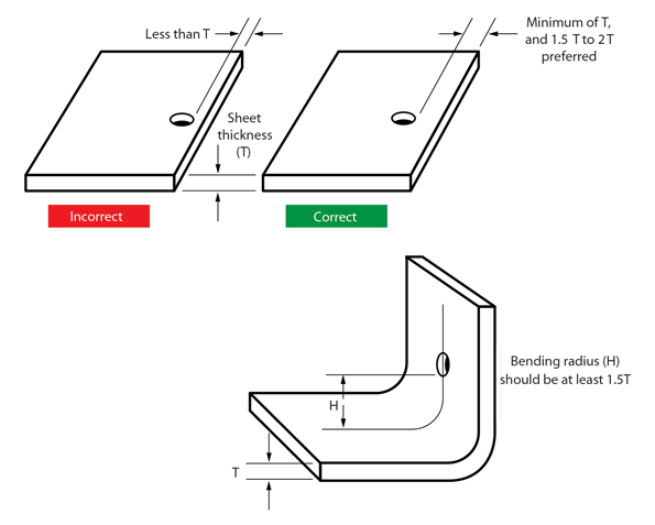
In low carbon steel sheet metal the minimum radius of a bend should be one half the material thickness or 0 80 mm.
The force must exceed the material s yield strength to achieve a plastic deformation.
A 1 degree tolerance on all bend angles.
Avoid large sheet metal parts with small bent flanges.
Sheet metal parts with a minimum of 0 9mm to 20mm in thickness can be manufactured.
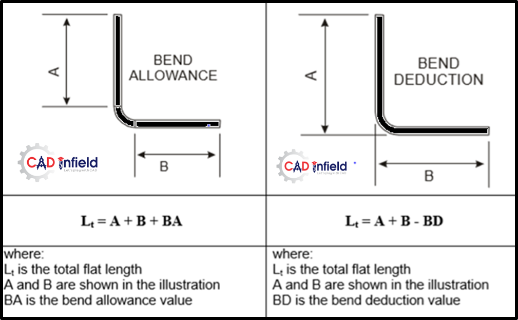
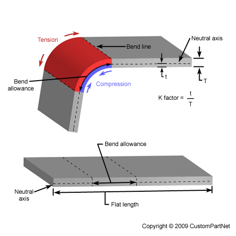
Therefore the bend allowance added to the flange lengths is equal to the total flat.
The minimum distance between two counterbores is eight times the material thickness.
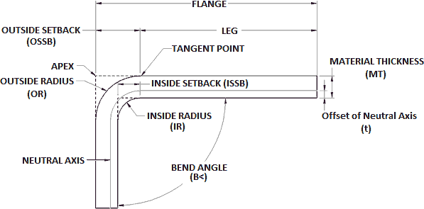
Material thickness mt the gauge of the material in decimal form.
Bend angle b the inside angle between the two legs or flanges of a bend.
Bend allowance ba the amount of added to the sum of the two leg lengths to obtain the flat pattern length.
Bend deduction bd the amount removed from the sum of the two flange lengths to obtain a flat pattern.
Which results in the increase of total surface area.
When designing parts for laser cutting one should not make holes smaller than the thickness of the material.
Therefore after bending total sheetmetal part length a b is greater than sheet metal flat length.
Bend deduction is equal to the difference between the total sheet metal length after bending and flat length.
Bending is one of the most common sheet metal fabrication operations.
In low carbon steel sheet metal the minimum radius of a bend should be one half the material thickness or 0 80 mm 0 03 inch whichever is larger counterbores.
The bend allowance describes the length of the neutral axis between the bend lines or in other words the arc length of the bend.
Also known as press braking flanging die bending folding and edging this method is used to deform a material to an angular shape.
This is done through the application of force on a workpiece.
Depending on the distance between the faces the bends are trimmed so that they are tangent or a face is created between the two bends.


